
Understanding LEDs on Metal-Core PCBs explores the crucial role that metal-core printed circuit boards play in the design and efficiency of LED applications. As demand for high-performance lighting solutions grows, the advantages offered by metal-core PCBs, especially their superior heat dissipation properties, become increasingly evident. This article aims to break down the technical and practical aspects of using metal-core PCBs in LED technology and will discuss design considerations, materials, manufacturing processes, challenges, and future developments in the field.
1. What Are Metal-Core PCBs and Their Benefits?
What exactly are metal-core PCBs, and why are they beneficial? Simply put, metal-core printed circuit boards consist of a metal substrate—typically aluminum or copper—rather than the more common FR-4 glass epoxy. This construction provides substantial advantages, particularly for LED applications. But here’s the kicker: the inherent thermal management capabilities of metal-core PCBs allow LEDs to operate at lower temperatures, thereby enhancing their lifespan and overall performance.
The most notable benefit of metal-core PCBs is their superior thermal conductivity compared to traditional PCBs. They channel heat away from the exposed components effectively, preventing overheating and potential failure. For LED applications, managing thermal energy is crucial. When LEDs generate light, they also produce heat. If this heat is not dissipated efficiently, it can lead to a reduction in light output and ultimately shorten the life of the LED.
Moreover, metal-core PCBs are designed to offer improved durability and mechanical strength, making them more reliable for long-term applications. This is particularly vital for products that undergo mechanical stress or temperature fluctuations. In sectors like automotive and outdoor lighting, the robustness of metal-core PCBs is indispensable.
To summarize, the transition from traditional PCBs to metal-core variants represents a significant innovation in LED technology, serving as a dependable method to enhance performance and extend the life of LEDs.
| Feature | Constant PCB | Metal-Core PCB |
|---|---|---|
| Heat Dissipation | Moderate | Excellent |
| Durability | Lower | Higher |
| Weight | Lighter | Heavier |
| Cost | Lower | Higher |
2. Why Are LEDs Used on Metal-Core PCBs?
Why is the combination of LEDs and metal-core PCBs so prevalent? The answer lies in the unique thermal management properties offered by these specialized PCBs. What’s the real story? The efficient heat dissipation afforded by metal-core substrates directly influences the performance and longevity of LEDs, making the pairing almost irresistible for designers.
One primary reason LEDs are utilized on metal-core PCBs is the impressive thermal conductivity. Unlike traditional PCBs, which can trap heat beneath the components, metal-core designs allow for rapid heat transfer away from the diode, effectively managing the temperature during operation. This feature is crucial because overheating can not only reduce the light output of an LED but may also cause permanent damage.
Additionally, metal-core technologies can accommodate larger assemblies of LEDs, creating brighter and more effective lighting solutions without overheating the components. This aspect becomes incredibly valuable in applications where high brightness is necessary, such as in automotive lighting or large display screens.
Furthermore, using metal-core PCBs enhances the overall reliability of LED products. As critical components increasingly operate in harsh environments, the mechanical stability offered by metal-core variants helps maintain performance levels. The heat management capability allows for more compact designs without compromising on thermal performance, leading to more space-efficient and cost-effective solutions.
So, it’s clear that operating LEDs on metal-core PCBs is not just about heat management; it is also about enhancing overall product reliability and efficiency.
| Benefit | Description |
|---|---|
| Heat Management | Efficiently channels heat away from LEDs |
| Longevity | Extends lifespan of components due to lower temps |
| Compact Design | Allows for smaller assemblies while maintaining performance |
3. How Do You Design Metal-Core PCBs for LEDs?
How do you go about designing metal-core PCBs for LED applications? This stage is where several engineering principles come into play. Ready for the good part? The design process can ensure that heat is managed effectively while still adhering to other electrical considerations.
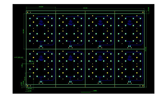
When designing metal-core PCBs for LEDs, the first thing to consider is the layout. The arrangement of components plays a pivotal role in how effectively heat is dissipated. Ideally, high-heat-generating components should be spaced to minimize thermal build-up while simultaneously being connected efficiently for optimal performance. Utilizing software tools like Altium Designer or Eagle can help visualize these layouts effectively, enabling better circuit design decisions.
Another crucial aspect is selecting appropriate materials. The metal substrate should be chosen based on its thermal and mechanical properties. Aluminum is commonly preferred for its excellent thermal performance and cost-effectiveness, while copper serves as a premium alternative with higher thermal conductivity.
Next, thermal vias should be incorporated into the design. These are plated holes that assist in transferring heat from the top side of the PCB to the metal core. This configuration dramatically increases the area available for heat transfer, facilitating improved heat management.
Furthermore, it’s essential to keep the manufacturing process in mind during the design phase. This means adhering to specifications that the PCB manufacturer can reliably implement. Any complex design may lead to increased production costs, so designing with manufacturability in mind is crucial.
In conclusion, effective design of metal-core PCBs for LEDs combines thermal, mechanical, and electrical considerations to optimize performance.
| Design Element | Importance |
|---|---|
| Layout | Affects heat dissipation and performance |
| Material Selection | Impacts thermal conductivity and durability |
| Thermal Vias | Enhances heat transfer efficiency |
4. What Materials Are Used in Metal-Core PCB Construction?
What materials are typically used in the construction of metal-core PCBs? Understanding the materials involved is crucial for anyone working with metal-core technology. This is where it gets interesting: the right materials can dramatically affect performance and longevity.
The base material for metal-core PCBs is typically a thick layer of metal, primarily aluminum or copper. Aluminum is favored for its balance of cost and thermal conductivity, providing excellent heat management without significantly increasing production costs. However, copper—a more expensive option—offers superior thermal performance and is often used in applications that require intensive thermal management, such as high-power LEDs.
For the dielectric layer, materials like polyimide or epoxy resin are commonly utilized. These materials provide electrical insulation while allowing for efficient thermal conduction. The dielectric layer acts as a barrier between the metal core and the circuit traces, ensuring that electrical signals can move without interference.
Moreover, surface finishes also play a role in metal-core PCB construction. Common finishes include gold, nickel, or HASL (Hot Air Solder Leveling), which prepares the PCB for soldering while also enhancing solderability and preventing oxidation.
Another important aspect is thermal interface materials (TIMs), which are often applied between the LED and the PCB to further enhance heat transfer. TIMs fill microscopic air gaps and imperfections, ensuring that heat travels efficiently from the LED to the metal substrate.
Selecting the right combination of materials is vital for ensuring optimal performance and reliability in metal-core PCBs for LED applications.
| Material Type | Purpose |
|---|---|
| Metal Substrate | Conducts and disperses heat |
| Dielectric Material | Provides insulation while facilitating thermal transfer |
| Surface Finish | Enhances solderability and prevents oxidation |
| Thermal Interface Material (TIM) | Improves heat transfer from LED to PCB |
5. How Does Heat Dissipation Work in Metal-Core PCBs?
How does heat dissipation function in metal-core PCBs? The thermal management capability is one of the standout features of metal-core PCBs, directly impacting both LED performance and lifespan. Let’s dive deeper into the mechanisms of heat dissipation to uncover the layers of efficiency.
The process begins with the generation of heat from the LED itself during operation. When electrical energy is converted into light, a certain amount of that energy is inevitably lost as heat. In standard PCBs, this heat is often trapped, leading to increased temperatures that significantly affect LED performance.
In contrast, metal-core PCBs leverage their metallic substrate to quickly disperse heat away from the LED. The heat generated will travel via conduction through the PCB material into the metal core, which then dissipates the heat into the surrounding environment.
What’s the real story behind this process? The effectiveness of heat dissipation relies heavily on factors such as the thickness of the metal substrate, the overall design of the PCB, and the environment where it operates. Thicker metal layers generally improve heat dissipation properties but may also lead to increased costs and weight.
Additionally, integrating thermal vias into the design enhances heat transfer efficiency. These small plated holes create a more extensive heat transfer pathway, allowing for more effective cooling even in tightly-packed circuits.
Understanding these mechanisms allows designers to optimize their metal-core PCB designs, balancing thermal conductivity with electrical performance to maximize the efficiency and lifespan of the LEDs they support.
| Mechanism | Description |
|---|---|
| Conduction | Heat moves from LED to metal substrate |
| Convection | Heat dissipated to surrounding air |
| Thermal Vias | Enhance heat transfer paths |
6. What Are the Manufacturing Processes for Metal-Core PCBs?
What manufacturing processes are involved in producing metal-core PCBs? These processes require specific expertise and technology to ensure that the final product meets the required quality and performance standards. Here’s where it gets exciting: understanding the manufacturing stages can significantly affect the outcome.
The manufacturing process begins with material selection. After selecting the metal substrate, dielectric materials, and surface finishes, the next step is to cut the metal layer into the required size. Precision is crucial at this stage, ensuring that the metal core is adequately aligned for subsequent processes.
Once the metal substrate is prepared, the dielectric layer is applied. This can be done through lamination, where the dielectric material is heated and pressed onto the metal substrate, ensuring strong adhesion without compromising performance.
Next comes the circuit patterning phase. This involves transferring the circuit design onto the dielectric layer. This can be accomplished using various methods, including photoengraving, where a photoresist layer is exposed to UV light, creating the desired pattern. Chemical etching is then used to remove unwanted copper and leave behind the necessary conductive traces.
After patterning, surface finishes like HASL, gold, or nickel are applied to enhance solderability and protect the PCB from oxidation. These finishes ensure that the PCB can be reliably soldered during the assembly process.
Finally, rigorous testing is conducted to guarantee that the finished metal-core PCB meets the required specifications. These tests often include inspecting the thermal properties and conducting electrical tests to verify functionality.
In summation, understanding the manufacturing processes involved in producing metal-core PCBs is essential for anyone looking to leverage this technology in LED applications.
| Manufacturing Stage | Process Description |
|---|---|
| Material Cutting | Preparing the metal substrate for further processing |
| Dielectric Layer Application | Adhesion of the insulating layer |
| Circuit Patterning | Creating electrical pathways using photoengraving and etching |
| Surface Finishing | Applying protective and solderable coatings |
| Testing and Quality Assurance | Ensuring the product meets requirements |
7. What Challenges Are Associated with Metal-Core PCBs?
What challenges can arise when working with metal-core PCBs? Despite their many advantages, certain hurdles can present obstacles during design and manufacturing. Here’s where it gets interesting: understanding these challenges allows for better planning and ultimately leads to more successful outcomes.
One key challenge is the increased complexity of the design process. Metal-core PCBs require specialized design considerations due to their unique properties, and failing to account for factors such as thermal vias can lead to ineffective heat management. This complexity can produce longer design times and may require additional training for engineers unfamiliar with metal-core technology.
Another challenge is the selection of appropriate manufacturing methods. Not all manufacturers have the equipment or expertise necessary for producing metal-core PCBs. This limitation can result in higher costs or longer lead times, especially if a designer must source materials or services from multiple vendors.
Moreover, there can be a greater risk of defects during the manufacturing process. Handling metal substrates involves careful precision; any mishandling during cutting or adhering layers can lead to issues like delamination or poor conductivity.
Finally, the overall cost of metal-core PCBs can be a barrier for some companies. While they provide long-term performance benefits, the initial investment is often significantly higher than that of traditional PCBs. This cost concern can lead companies to hesitate about fully transitioning to metal-core technologies.
By being aware of these challenges, designers and manufacturers can strategize effectively, ultimately resulting in better-designed products that take full advantage of the benefits offered by metal-core PCBs.
| Challenge | Solution |
|---|---|
| Design Complexity | Invest in training and resources |
| Manufacturing Limitations | Select specialized manufacturers |
| Defect Risks | Implement strict quality control measures |
| Cost Concerns | Analyze long-term savings vs. short-term costs |
8. How Do You Assemble LEDs on Metal-Core PCBs?
How do you effectively assemble LEDs on metal-core PCBs? This stage is critical for ensuring the performance and reliability of LED lighting solutions. What’s the real story? The assembly process can significantly affect how well the LEDs operate in conjunction with the metal-core PCB.
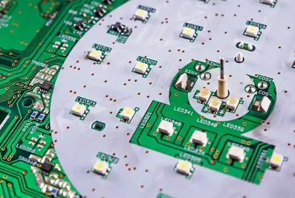
The first step in assembly is to ensure proper alignment and placement of the LEDs on the PCB. An accurate placement is paramount; any misalignment can lead to inefficient heat dissipation and potential performance issues. Utilizing tools like pick-and-place machines can automate this process, enhancing precision while saving time.
Next, soldering is crucial in securing the LEDs to the PCB. There are several techniques available, but surface mount technology (SMT) is commonly used for its effectiveness with metal-core designs. In this process, solder paste is applied to designated pads on the PCB, then heated to create electrical connections with the LEDs.
Thermal interface materials (TIMs) should also be applied between the LEDs and the PCB to improve thermal conductivity. This ensures better heat transfer from the LED to the metal substrate, which is vital for preventing overheating.
After soldering, visual inspection and automated testing should be conducted to verify that the assembly is flawless. This step helps catch any defects that could impede the performance of the LEDs. Following assembly, the entire unit should undergo functionality testing to ensure it meets design specifications and performance criteria.
In summary, assembling LEDs on metal-core PCBs involves a series of meticulous steps focused on placement accuracy, soldering techniques, and thorough testing to ensure optimal performance.
| Assembly Step | Description |
|---|---|
| Alignment and Placement | Precise positioning of LEDs on the board |
| Soldering Techniques | Using SMT for secure connections |
| Thermal Interface Application | Enhances thermal transfer to metal core |
| Inspection and Testing | Verifying assembly quality and functionality |
9. What Testing Methods Are Essential for Metal-Core PCB Assemblies?
What testing methods are essential for ensuring high-quality metal-core PCB assemblies? This critical stage helps confirm that the product will perform effectively and reliably. Here’s where it gets interesting: implementing rigorous testing protocols can catch potential failures before they lead to costly repercussions.
The first testing method is functional testing, which assesses whether the metal-core PCB operates as intended. During this phase, all electrical pathways and connections are checked to ensure current flows without issues. This step can involve simulated usage conditions to evaluate real-world performance.
Thermal testing is another vital procedure. Monitoring temperatures during operation will help determine how effectively the PCB dissipates heat. This test is especially important for LED applications, where excessive heat can lead to reduced performance and component failure.
Mechanical testing is also necessary to ensure the PCB can withstand physical stressors. This can include vibration and shock testing to assess how the assembly behaves under dynamic conditions. Such testing is crucial for applications in automotive or industrial settings where components might be subject to harsh environments.
Lastly, quality assurance methodologies—such as automated optical inspection (AOI)—provide a way to quickly identify defects in the soldering or alignment of components. These systems can scan PCBs during production and flag any irregularities, ensuring that only the highest quality products reach the market.
By embracing these comprehensive testing methods, manufacturers can guarantee that their metal-core PCB assemblies meet high standards for performance and reliability.
| Testing Method | Purpose |
|---|---|
| Functional Testing | Ensure the PCB operates correctly |
| Thermal Testing | Verify effective heat dissipation |
| Mechanical Testing | Assess durability under physical stress |
| Quality Assurance | Use AOI to catch defects during production |
10. What Applications Benefit from Using LEDs on Metal-Core PCBs?
What applications can significantly benefit from the use of LEDs on metal-core PCBs? The versatility of this technology is impressive, making it suitable for various sectors. So, what’s the real story? Understanding these applications can help businesses leverage benefits unique to metal-core PCB technology.
One significant application is in automotive lighting. The need for bright, reliable light sources that can handle high levels of heat makes metal-core PCBs ideal for car headlights and taillights. The efficient heat dissipation directly contributes to longer LED lifespans in vehicle lighting systems.
Another application involves outdoor displays, such as billboards or stadium screens. These displays require high-intensity lighting capable of operating efficiently in daylight and night conditions. Metal-core PCBs help maintain brightness without overheating, ensuring consistent performance.
In industrial settings, metal-core PCBs are used for machine lighting, inspection systems, and safety lights. The ability to endure the rigors of harsh environments while providing reliable performance is invaluable in this sector.
Additionally, metal-core PCBs find their place in consumer electronics, where powered devices—like TVs and monitors—depend on efficient cooling to maintain high quality without failure. The compact designs characteristic of metal-core technology allow for sleek product forms in consumer devices.
Overall, the scope of applications benefiting from LEDs on metal-core PCBs is broad, with the potential for many more advancements as technology continues to evolve.
| Application Area | Description |
|---|---|
| Automotive Lighting | Durable, heat-resistant for vehicle lights |
| Outdoor Displays | Bright, efficient light for billboards |
| Industrial Lighting | Robust solutions for machine and safety lights |
| Consumer Electronics | High-quality lighting for TVs and monitors |
11. How Do Cost Considerations Affect the Use of Metal-Core PCBs?
How do cost considerations impact the adoption of metal-core PCBs? While the benefits are clear, the investment required for this technology can be a topic of discussion. What’s the kicker here? Understanding the long-term savings versus upfront costs can guide decision-making.
Initially, metal-core PCBs are typically more expensive than standard FR-4 PCBs. This price difference arises from the materials and manufacturing processes involved. Aluminum or copper substrates often have higher raw material costs, and the specialized techniques required for producing quality metal-core PCBs can contribute to higher labor costs.
However, the increased efficiency and durability of metal-core designs can lead to significant long-term savings. First, the enhanced thermal management reduces the likelihood of LED failure, which translates to fewer replacements and repairs over time. For companies with significant production and maintenance budgets, this reliability can yield substantial savings.
Next, energy efficiency plays a role as well. Metal-core PCBs can improve the energy efficiency of an LED product, lowering electricity consumption and, consequently, utility costs. This aspect is particularly important for businesses operating in sectors where energy costs are a significant line item, such as manufacturing or retail.
Finally, developers should consider the potential for market differentiation. Metal-core PCBs enable the production of high-performance, compact designs that can set a product apart in a competitive market. This differentiation can lead to higher margins on products, counterbalancing the initial investment.
In conclusion, while the upfront costs of adopting metal-core PCBs can be higher, the long-term benefits can make them a worthwhile investment for many businesses.
| Cost Factor | Impact on Decision-Making |
|---|---|
| Material Costs | Higher initial investment |
| Durability | Reduces long-term maintenance costs |
| Energy Efficiency | Potentially lowers operational expenses |
| Market Differentiation | Opportunities for better profit margins |
12. What Future Developments Can We Expect in Metal-Core PCB Technology?
What future developments should we be on the lookout for in metal-core PCB technology? As innovation continues to unfold, exciting advancements are on the horizon. Ready for the good part? These developments may redefine how metal-core PCBs are utilized in various industries.
One major development we may see is the evolution of materials. There is ongoing research into utilizing new composite materials that could offer even higher thermal conductivity while keeping costs down. As material science evolves, the combination of metals with alternative insulating materials could lead to more efficient designs that cater to the growing demand for advanced LED solutions.
Moreover, the integration of smart technologies into metal-core PCBs could see increased adoption. As IoT devices proliferate, the need for intelligent lighting solutions becomes paramount. Metal-core PCBs may evolve to include integrated sensors that monitor heat levels and control LED brightness accordingly, optimizing energy usage.
Additionally, advancements in manufacturing processes hold great promise. Techniques such as 3D printing or automated assembly could streamline production, decrease waste, and reduce costs. Companies are already exploring these methods to improve flexibility in design and manufacturing.
Lastly, as regulatory pressures increase, particularly related to environmental standards and sustainability, metal-core designs could evolve to incorporate eco-friendly materials and manufacturing practices. This shift could make them more appealing in markets focused on sustainability and reducing carbon footprints.
In essence, staying abreast of these upcoming developments in metal-core PCBs can provide businesses with insights into optimizing their designs and maintaining competitiveness.
| Future Development | Potential Impact |
|---|---|
| Material Innovations | Higher performance with lower costs |
| Smart Integrations | Enhanced functionality for IoT applications |
| Advanced Manufacturing | More efficient and flexible production methods |
| Sustainability Focus | Eco-friendly materials and practices |
13. How Do Regulations and Standards Affect Metal-Core PCB Production?
How do regulations and standards impact the production of metal-core PCBs? Compliance with these benchmarks is not just critical; it’s a non-negotiable aspect of ensuring product quality and market readiness. What’s the kicker? Understanding these factors can aid in navigating complex manufacturing requirements.
In many countries, metal-core PCB production must adhere to specific industry standards such as IPC-A-600, which governs the acceptability of printed circuit boards. Such standards ensure quality and performance metrics are met, aiding in eliminating defects that could otherwise lead to failures in the field.
Additionally, safety regulations also play a crucial role. In sectors like automotive or aerospace, compliance with stringent safety guidelines is essential. Failing to meet these regulations can result in severe penalties and reputational damage, making it imperative for manufacturers to prioritize compliance in their processes.
Moreover, standards related to environmental considerations, such as RoHS (Restriction of Hazardous Substances), are increasingly relevant. RoHS-compliant metal-core PCBs must avoid the use of certain harmful substances during production, ensuring that the products not only perform well but are safely disposed of at the end of their life cycle.
By keeping abreast of these regulatory landscapes, manufacturers can better position themselves to create products that are not only high-performing but also compliant with legal and environmental requirements.
| Regulation/Standard | Purpose |
|---|---|
| IPC-A-600 | Sets quality acceptance criteria |
| Safety Regulations | Ensures products meet safety standards |
| RoHS Compliance | Restricts hazardous substances in production |
14. What are Best Practices for Working with Metal-Core PCBs?
What are the best practices for working with metal-core PCBs to achieve optimal results? Implementing effective strategies can significantly influence both design and manufacturing efficiency. Let’s explore these practices to ensure that your projects turn out successful.
One best practice is thorough documentation throughout the design and manufacturing processes. Keeping detailed records of specifications, materials, and revisions ensures that all team members are on the same page, minimizing miscommunications and errors during production.
Next, always take into account the specific thermal requirements of the LEDs being used. Ensure that the design includes provisions for thermal vias, sufficient space for heat dissipation, and proper alignment of LEDs for maximum thermal contact. These considerations can dramatically influence the efficiency of heat management.
Additionally, regularly engage in cross-team collaboration, especially among design, manufacturing, and quality assurance teams. Sharing insights can lead to innovative solutions that enhance performance and reduce costs, ultimately resulting in a more robust product.
Finally, consider creating prototypes for testing before full-scale production. Prototyping allows you to assess heat management, functionality, and overall design integrity, providing invaluable feedback to refine your final designs.
By adhering to these best practices, you can elevate the performance and reliability of metal-core PCBs in your projects, ensuring a successful outcome.
| Best Practice | Reason |
|---|---|
| Thorough Documentation | Minimizes miscommunication errors |
| Thermal Considerations | Ensures effective heat dissipation |
| Cross-Team Collaboration | Fosters innovation and problem-solving |
| Prototyping | Validates design choices before mass production |
15. How Can You Stay Updated on Metal-Core PCB Technologies?
How can professionals remain current with developments in metal-core PCB technologies? Staying informed is vital for maintaining a competitive edge in a rapidly evolving industry. What’s the kicker? Engaging with the right resources can make all the difference.
Subscribing to industry journals and newsletters is a straightforward way to keep up with trends and techniques. Publications like PCB Magazine or online forums provide insights into emerging technologies and best practices, enriching your understanding of metal-core PCB technology.
Joining professional organizations, such as IPC or IEEE, can also provide access to events, networking opportunities, and specialized training programs. These memberships offer a platform for sharing knowledge and forging relationships with others working in the field.
Attending trade shows and industry conferences can be incredibly beneficial as well. Events like the IPC APEX EXPO offer face-to-face interactions with experts, highlighting the newest products and methodologies in PCB technology.
Participating in online courses or webinars can also enhance your expertise. Many organizations offer specialized training, allowing professionals to learn about the latest advancements in their own time.
By actively engaging with these resources, professionals can ensure that they remain knowledgeable about the latest developments in metal-core PCB technologies, positioning themselves as leaders in the industry.
| Resource Type | Benefit |
|---|---|
| Industry Journals | Stay informed about trends and innovations |
| Professional Organizations | Networking and training opportunities |
| Trade Shows | Discover new products and technologies |
| Online Courses | Flexibility in learning about advancements |
FAQ Section
Q1: What are metal-core PCBs?
Metal-core PCBs are printed circuit boards constructed with a metal substrate, usually aluminum or copper, that provide superior thermal management for applications like LEDs.
Q2: How does heat dissipation work in metal-core PCBs?
Heat dissipation in metal-core PCBs occurs through effective conduction from the LED to the metal core, which then transfers heat to the surrounding environment, ensuring optimal operating temperatures.
Q3: What materials are typically used in metal-core PCB construction?
Common materials include aluminum or copper for the metal substrate, dielectric materials like polyimide or epoxy resin, and surface finishes that enhance solderability.
Q4: What are the testing methods for metal-core PCB assemblies?
Essential testing methods include functional testing to verify operation, thermal testing to check heat management, and quality assurance techniques like automated optical inspection.
Q5: What applications benefit from using LEDs on metal-core PCBs?
Applications include automotive lighting, outdoor displays, industrial equipment, and consumer electronics, all of which require efficient heat management for optimal performance.